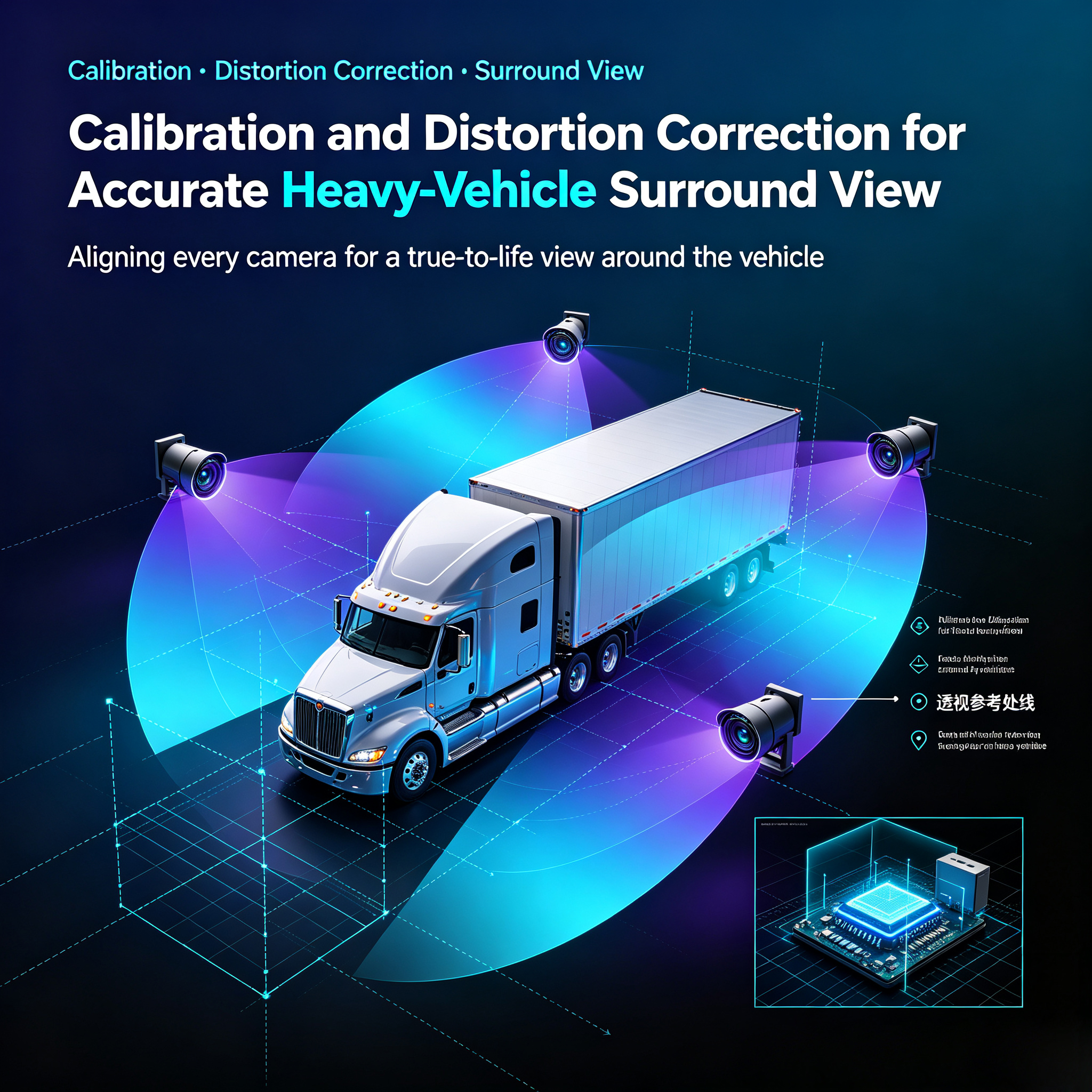
Calibration and Distortion Correction for Accurate Heavy-Vehicle Surround View
Accurate surround view depends on disciplined setup. This guide examines calibration targets, mounting geometry, lens modeling, distortion correction and post-installation verification for heavy vehicles operating under vibration, load variation and changing environmental conditions.
The system combines 360° Bird View System, Heavy-duty Vehicle, Blind Spot Elimination, Image Stitching, Camera Calibration, Distortion Correction, Night Vision, Fleet Safety, Accident Avoidance, and Return on Investment as one operating model.
Calibration Geometry
Calibration establishes the relationship between each lens, the vehicle body and the ground plane. Technicians record mounting height, angle, orientation and target points, then generate parameters that transform every image into the shared surround-view coordinate system.
Correcting Lens and Mounting Error
Wide-angle lenses bend straight lines and compress distance near the edges. A correction model must remove that error without creating excessive stretching. Mounting tolerance, body flex and load changes should be considered because they can shift the apparent position of nearby objects.
Verification and Maintenance
After installation, verify measured reference points at the front, rear and both sides. Recheck after camera replacement, body repair or major suspension work. A maintenance log should record calibration status, lens condition and software version.
Implementation Checklist
Use repeatable targets, record vehicle geometry, validate every overlap zone and define recalibration triggers. The acceptance test should confirm that objects remain correctly positioned around the vehicle under representative operating conditions.
For governance, teams should review 360° Bird View System, Heavy-duty Vehicle, Blind Spot Elimination, Image Stitching, Camera Calibration, Distortion Correction, Night Vision, Fleet Safety, Accident Avoidance, and Return on Investment together rather than as isolated features.